Schematic and PCB Design

Punoscho is having experience of Schematic and PCB Design in three Major Industry Standard Software – Eagle, Altium and in KiCAD. We are fully capable to design Modular Schematic, convert it to a PCB which can be a multilayer design.

To get the quote, Kindly fill up the form on the right side.

Kindly call us or send a message in WhatsApp at +91 9163986431

You can also drop us an email at contact@punoscho.in.

Schematic Design

We are fully capable to design in Autodesk Eagle, Altium and KiCAD. We have license for both the Autodesk Eagle which is now moved to Fusion 360 and the Altium 360. KiCAD is a free design software.

You can download sample of our schematic design from the below link –

Why Punoscho Schematic is Special?

Exactly. Why us? Well, in engineering, document is everything. Preparation of  Engineering Document is an Art in itself. If you checked the sample of our schematic, you already understood our capabilities and schematic highlights. If not please summarize this in below points –

  1. Our schematic is properly created
  2. Free of Errors
  3. All information’s are given related with circuit
  4. All crucial Voltage or information available for Embedded Engineers
  5. All the components will have attributes
  6. Maximum Flexibilities / options to add features without making new schematic design in the future.
  7. Properly highlighted key points.
  8. Anybody could read our schematic to debug issues in the future
  9. Designed with hierarchal model to understand circuit flow
  10. Properly crafted with time.

Capabilities

PCB Design Capabilities

We are fully capable to convert the schematic to a PCB Design. We have proper expertise ranging from general PCB Design to High speed PCB Design.

Below are the some points and Capabilities of us-

  1. Design Capabilities in Rigid and Rigid-Flex, Flex PCBs
  2. Upto 8-Layers
  3. Buried and Blind Vias with micro Vias Extension
  4. Proper FAN Our tactics for BGA Packages
  5. EMI Constrained Design
  6. Experience for DDR, HDMI, Ethernet, USB2.0-3.0, PCIe Tracing
  7. Impedance controlled Design
  8. RF expertise upto 10 Ghz.
  9. Power Traces
  10. Thermal Compensated Design for High Power PCBs

Proper PCB Spec doc will be available to understand the crucial points of the design/PCB board, that can be useful for PCB Production.

DFM Generation Capabilities

We understand that the DFM is important for making the PCB from concept to a Reality.

You can expect following files from us –

  1. Gerber Files
  2. BOM Files
  3. Pick-n-Place Files
  4. 3D-images
  5. 3D-Steps
  6. Images-2D
  7. Schematic
  8. PCB Spec-doc
  9. Other mechanical Files (If required or asked by the customer)

Please Note:

  1. We provide all source files to our customer free of cost.
  2. All Files are the property of our customer and we do not retain any files. Also, if any NDA Agreement is required, kindly send us the NDA first where the NDA should address to

    M/s Punoscho

    2/1F Thyackwell Road
    Liluah, Howrah – 711202
    +919163986431


Information and Sample of generated files from PCB or circuit design

Gerber Files

This is having the Board layout information for the PCB manufacturing including Drill file in Excellon. It is the main PCB File that will be used by the fabricator.

Click the below link for the Gerber File Samples –

BOM Files

This is the bill-of material file and it is another important document for a project. It is having manufacturing part-number and designation. Useful for procure component and what is what in the PCB. The BOM comes with Manufacturer part number (MFR-PN) and Manufacturer (MFR). We often provide the targeted Vendors where you can procure part depending on your requirement. It can be Element14, Digikey, mouser or can be Us, Punoscho. If you want us to supply parts, we are happy to help you, if you choose others we can help you in that case as well.  Sometimes, the possible vendor links are also given on the BOM, so you do not have to spent time on this.

Do not order the DNP tagged components. DNP means Do Not Populate. This components maybe required for modifications of the circuit without spending money on design changes as well as ordering new modified PCBs.

To understand how detail our BOM Document is, Kindly click the link below –

Pick-n-Place Files

Useful for Automated assembly. This file will be used by the PCB assembler to know and set there machine about the co-ordinates of the components.

For sample of our Pick-n-Place, Kindly click the link below –

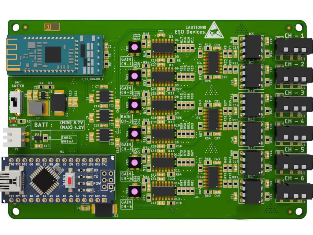
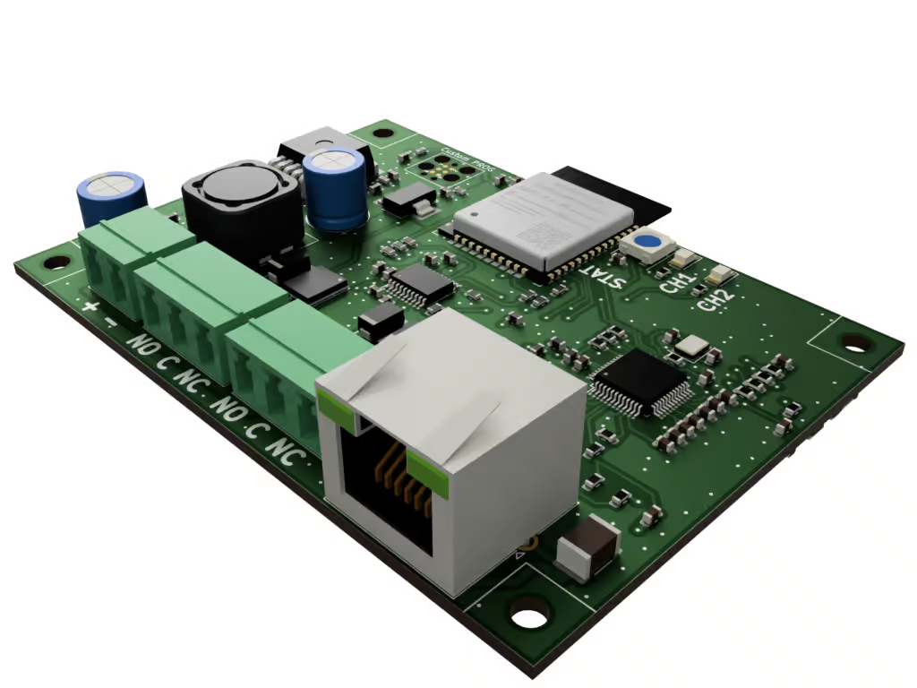
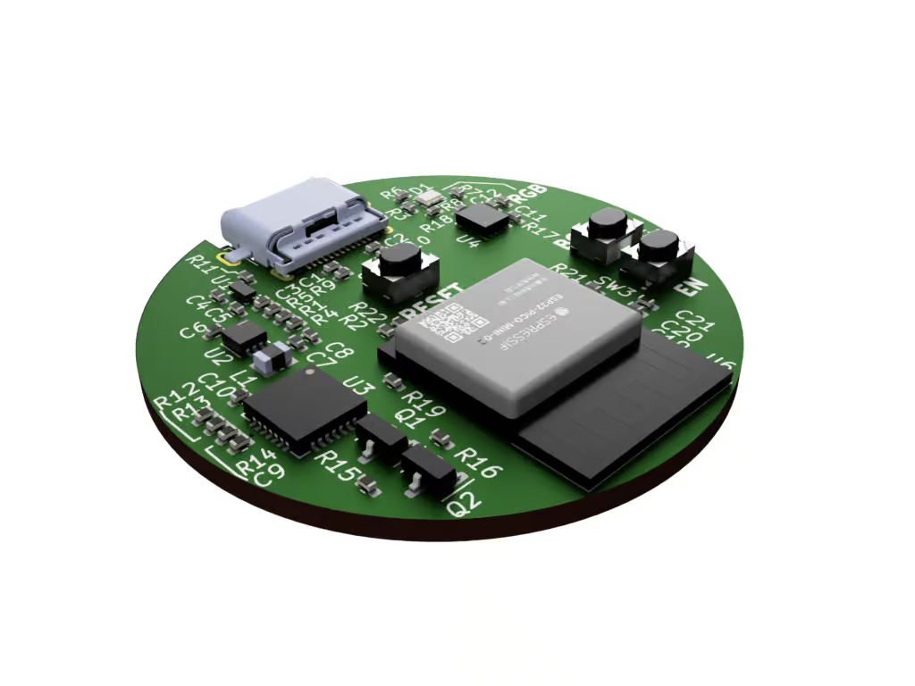
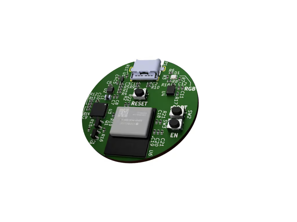
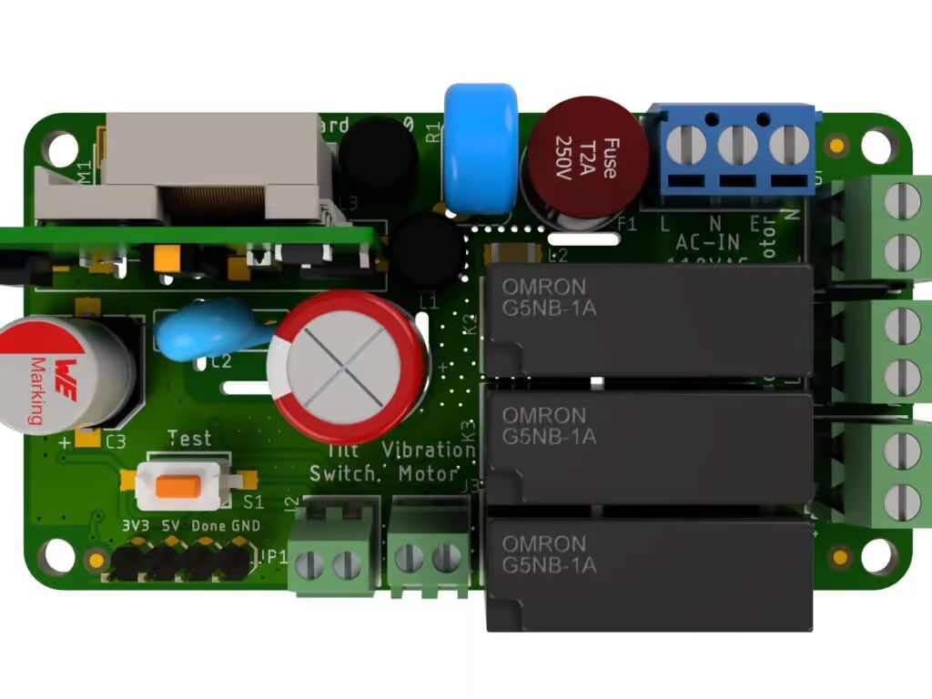
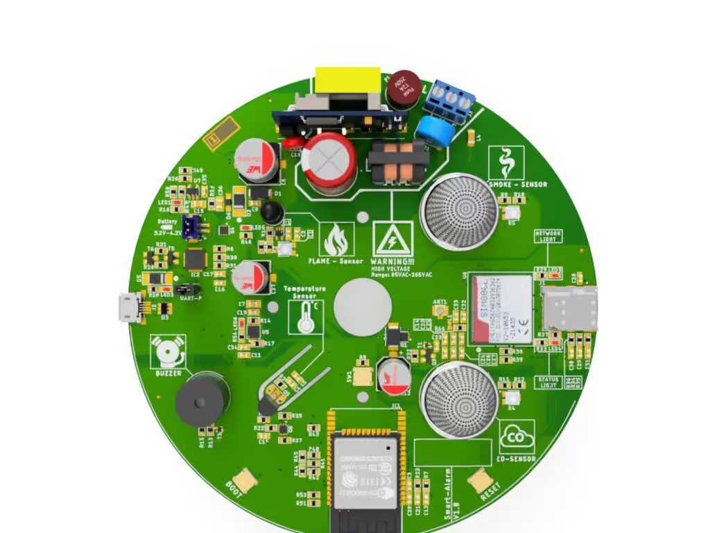
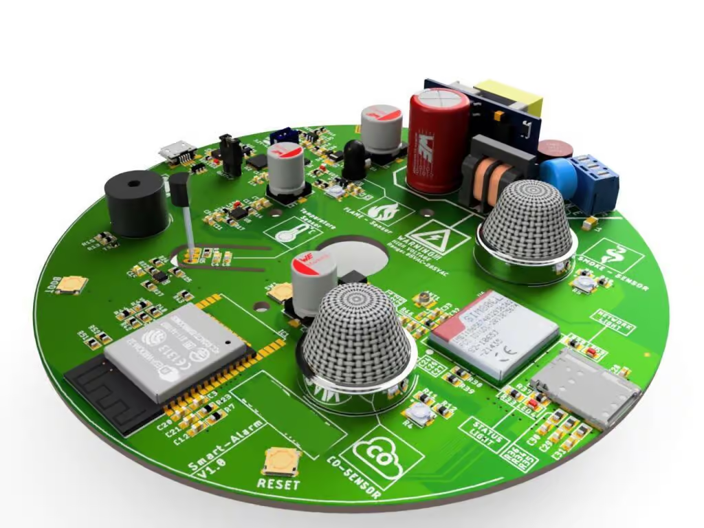
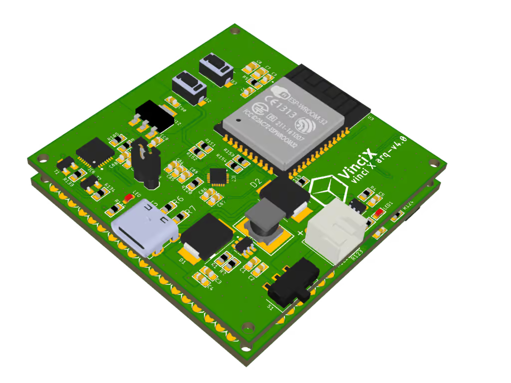
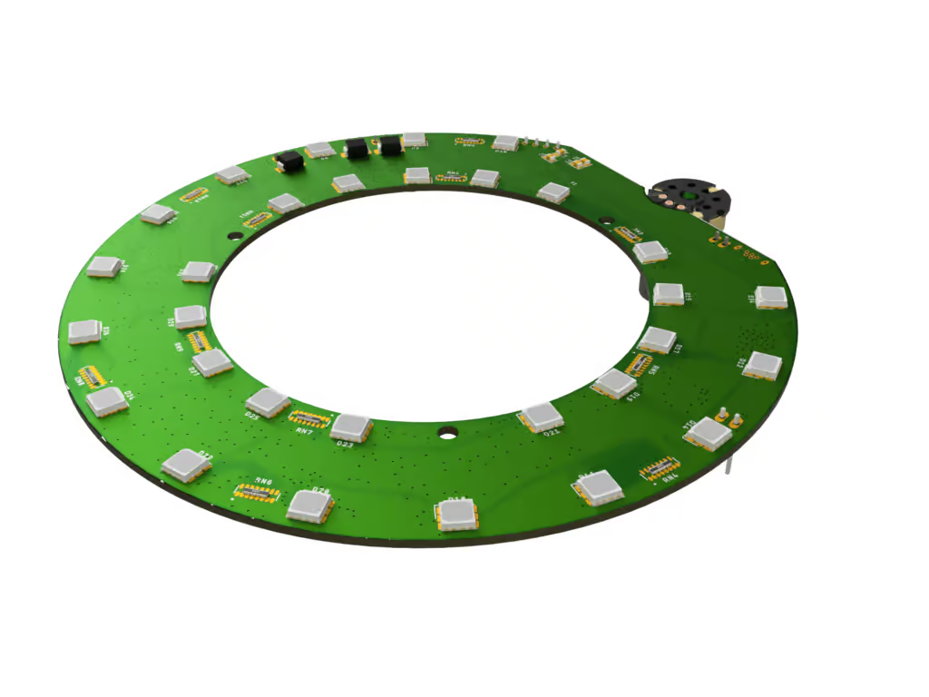
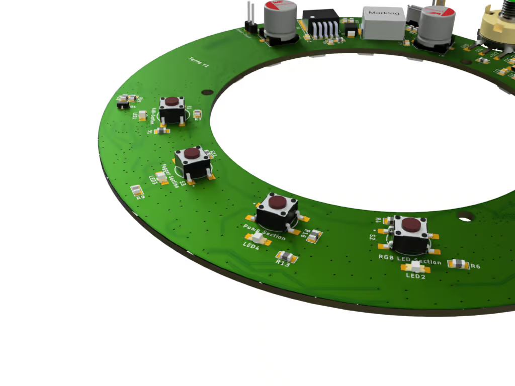
3D-images

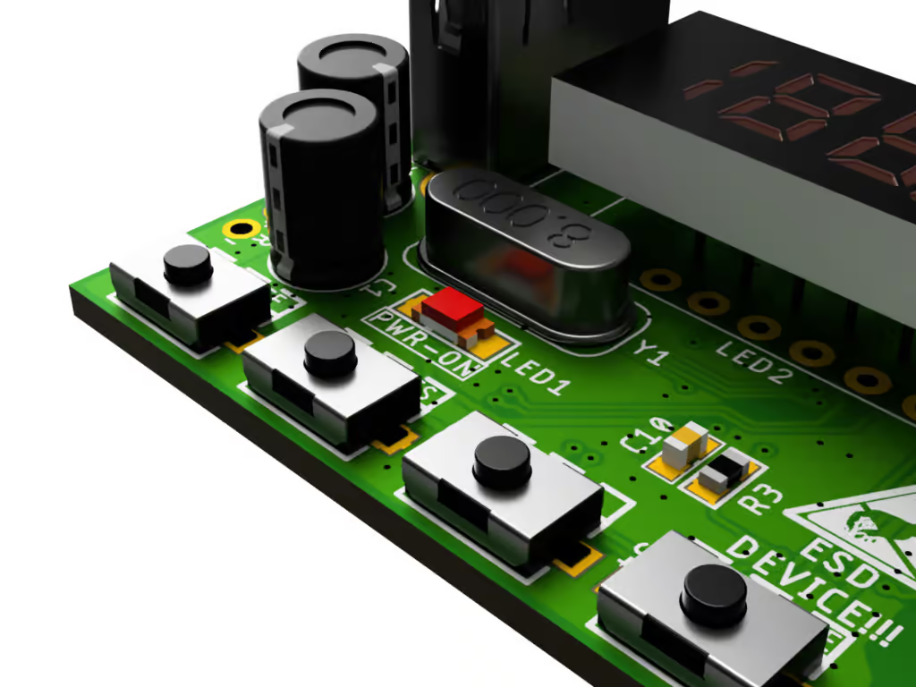
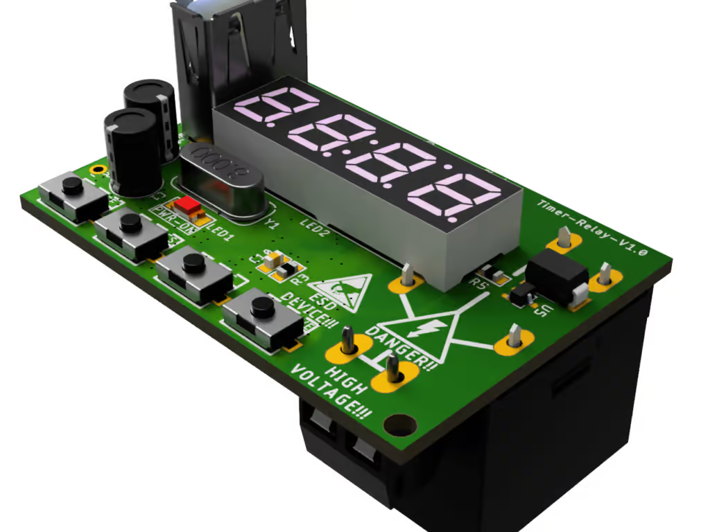
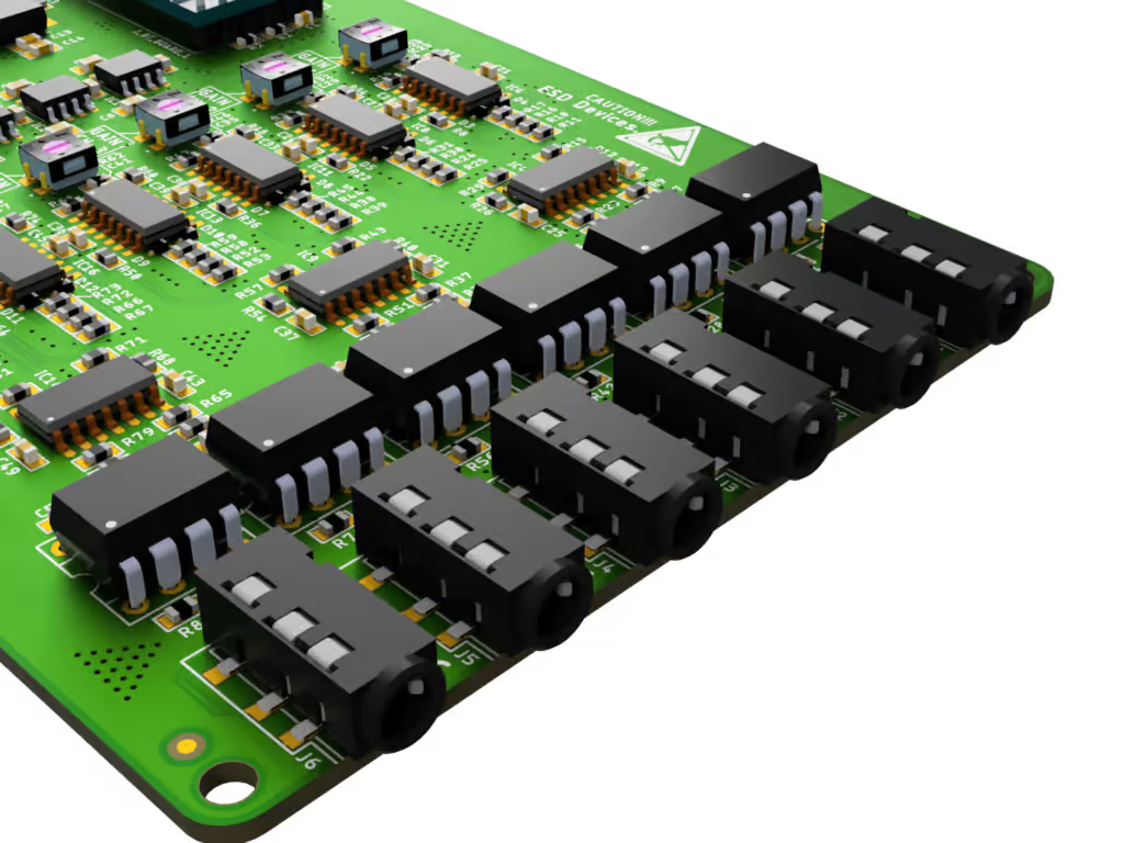
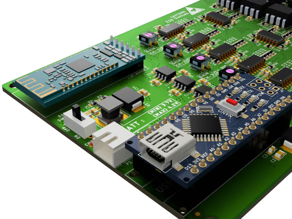
Useful for Visualize your Product. Before going to Production or Prototype, You could actually see the product in actual form about how it will look.

3D-Steps

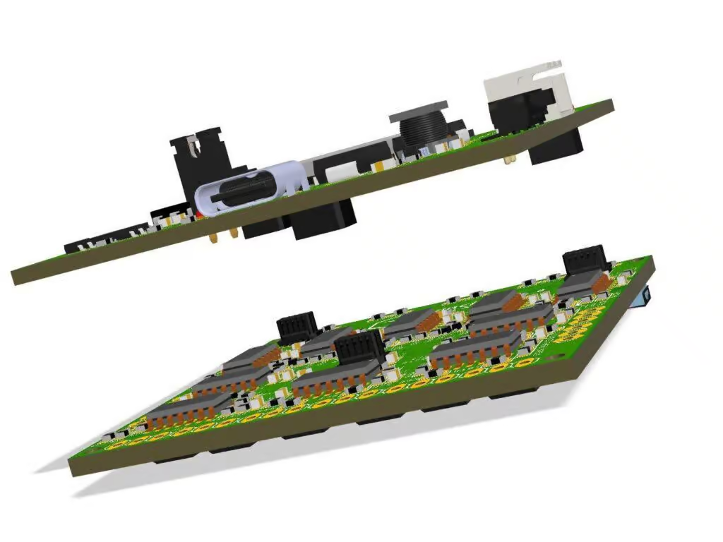
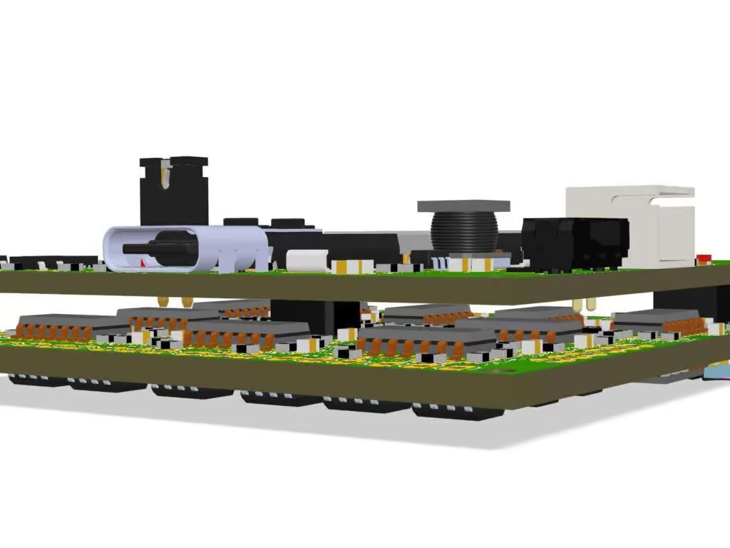
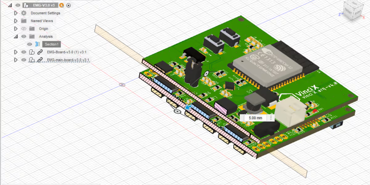
Mechanical Step File of the 3D. It is an important file if you are creating a product that is having predefined shape, box or assemblies. Before making the PCB, You can actually check the overlapping or not fitment issues using this file. If you provide the step file of the assembly, we can test by ourself before generating the manufacturing Files.

sectional-analysis

Images 2D

This is 2D images of the silk screen Layer. Used for Silk screen evaluation.

Schematic in PDF

The Schematic sample is already given in the first place. We can provide schematic in pdf as a DFM file.

PCB Spec Doc

This is another document having every single information’s about your PCB. It will contain board size, layer, lamination or silk screen information’s, drill specs etc.

To check the sample of this document, click the link below –